Número de teléfono:0086-0577-61731588
Fax:0086-0577-61731588
Teléfono móvil:+86 18072180777
Wechat:+86 18072180777
Sitio web:es.china-relay.com
Zona industrial de Zhiguang, ciudad de Liu, Yueqing, Zhejiang, China

Power supply voltage: 220VAC 50/60Hz;(2) 100-240 vac/DC
Allowable voltage variation range: 90-110% of supply voltage
Power consumption: below 8VA
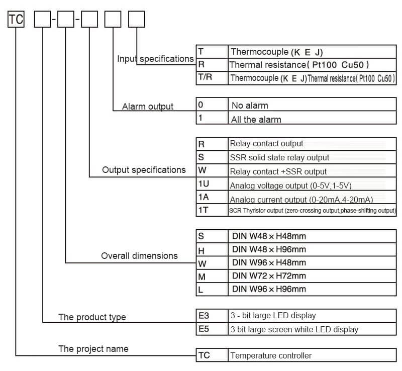
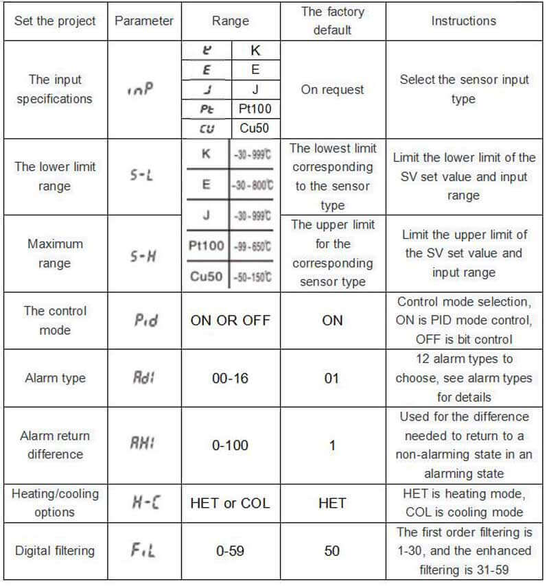
Input specification: Thermocouple :K, E, J
Thermal resistance :Pt100 Cu50
Display accuracy :±0.5%
Input specification: relay 250VAC 5A one on one off
SSR 12VDC±2V 20mA or less
Analog voltage output (0-5V, 1-5V)
Analog current output (0-20mA, 4-20mA)
SCR Silicon controlled output (zero crossing output, phase shifting output)
Presta atención a la seguridad
※ "Preste atención a la seguridad" es para el uso seguro y correcto del producto para evitar la ocurrencia de accidentes peligrosos. Tenga en cuenta los siguientes contenidos.
※ Atención La seguridad se puede dividir en dos partes: "advertencia" y "atención". El significado es el siguiente:
⚠ una advertencia, como la infracción de esta, puede provocar lesiones graves o la muerte.
⚠ atención, como en caso de violación de esto, puede resultar en lesiones menores o daños al producto.
⚠ advertencia
1.Se instalarán dispositivos de protección de seguridad doble antes del uso de las máquinas (como control de energía nuclear, equipo médico, barcos, vehículos, ferrocarriles, aviación, equipo de combustión, dispositivos de seguridad y dispositivos de prevención de desastres / robo) que tengan un impacto significativo impacto en la vida humana y la propiedad.
De lo contrario, podría provocar un incendio, lesiones personales o daños materiales.
2. El panel debe instalarse cuando se usa.
De lo contrario, existe riesgo de descarga eléctrica.
3. No realice trabajos de mantenimiento cuando esté encendido.
De lo contrario, existe riesgo de descarga eléctrica.
4. Confirme el número de terminal antes de la conexión.
Podría provocar un incendio.
5. El producto no podrá ser modificado excepto el personal de mantenimiento de la empresa.
De lo contrario, podría provocar una descarga eléctrica o un incendio.
⚠nota
1. No utilice este producto al aire libre.
De lo contrario, la vida útil del producto se acortará o se producirá un accidente por descarga eléctrica.
2.Cuando conecte el extremo de entrada de la fuente de alimentación con el extremo de salida del relé, utilice un cable AWG 20 (0,50 mm2) y mantenga el par de apriete del tornillo en 0,74 N.m ~ 0,90 N.m.
Un mal contacto puede provocar un incendio.
3. Utilice el producto dentro de la especificación nominal.
De lo contrario, la vida útil del producto se acortará y habrá peligro de incendio.
4. Utilice cargas inferiores a la capacidad permitida de los contactos de relé.
De lo contrario, provocará un aislamiento deficiente, uniones de contacto, un contacto deficiente, daños en el relé, fuego, etc.
5. No use agua o solventes orgánicos al limpiar, y limpie con una toalla seca.
Podría provocar una descarga eléctrica o un incendio.
6.Evite usar el producto en lugares inflamables, explosivos, húmedos, con luz solar directa, radiación térmica, vibraciones y otros lugares.
Podría provocar un incendio o una explosión.
7. No permita que entren polvo o residuos de cables en el producto.
De lo contrario, podría provocar un incendio o dañar el producto.
8.Después de confirmar la polaridad de los terminales, conecte el cableado del termopar correctamente.
De lo contrario, podría provocar un incendio o una explosión.
9. Con el fin de mejorar el aislamiento, utilice una fuente de alimentación que garantice el aislamiento mejorado.
Código de modelo
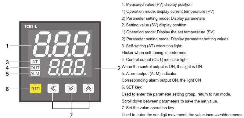
Name of each part
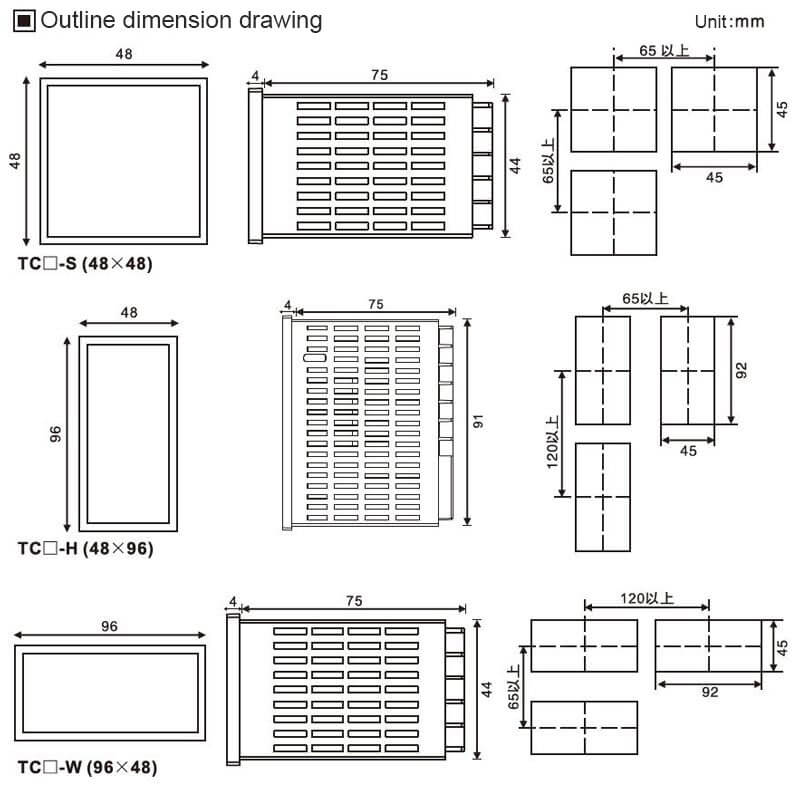
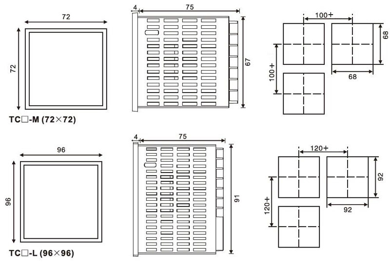
Dibujo de dimensiones exteriores
Especificaciones funcionales
1.Autoajuste[ ]
]
El autoajuste PID es la función del controlador de temperatura para calcular los parámetros de control PID midiendo las características térmicas y el tiempo de respuesta térmica del objeto de control, y a través de esta función puede realizar la configuración automática de parámetros para completar un control estable y de alta velocidad.
※ Al autoajustar, el sistema de calefacción debe estar en condiciones de trabajo y el valor medido PV debe ser menor que el valor establecido SV.
※ Cuando el parámetro del modo de control está en el estado de "
 ",el interruptor de autoajuste[
 ]será mostrado.
※ Configure el interruptor de autoajuste[]al estado de "", y la luz indicadora AT comienza a parpadear, lo que indica que se ha ingresado al estado de autoajuste.
※ Durante la ejecución del autoajuste, se bloquearán todos los grupos de parámetros y los valores de ajuste de SV. Si desea interrumpir el autoajuste manualmente, configure el interruptor de autoajuste[]al estado de " ".
".
※ Durante el autoajuste, si el código de falla" "o"
"o" "ocurre, se interrumpirá automáticamente.
※ Una vez finalizado el autoajuste, el indicador AT dejará de parpadear y los parámetros obtenido de la configuración se guardará automáticamente, y regresa el estado de control para continuar ejecutándose con un nuevo isoparámetro.
※ Interrumpir el autoajuste,los parámetros no se modificarán.
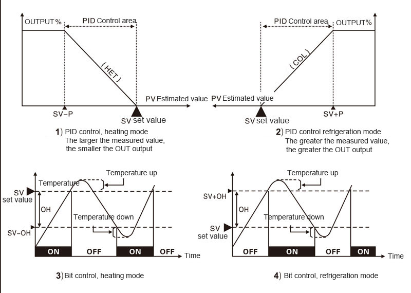
2.modo de control
Modo de controlparámetros bajo el estado de "", el modo de control PID actual, si está en el estado de"",es un estado de control de bits.
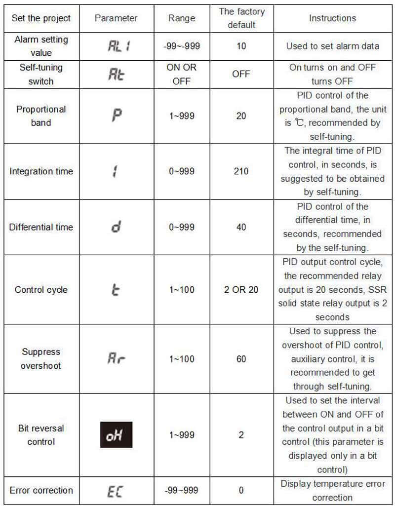
3.Suppress overshoot [ ]
]
For PID control, overshoot suppression adjustment, the larger the set value, the faster the heating, easy to overshoot;The smaller the setting value, the slower the heating and not easy to overshoot.Factory default is 60. It is recommended to get the set value by PID self-tuning.
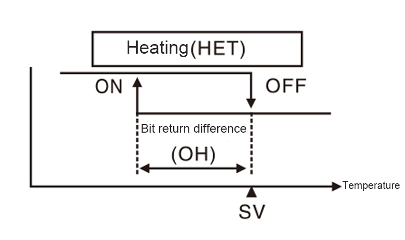
4.Bit control return difference[ ]
]
Used to set the interval between ON and OFF of the control output in a bit control.
※When the control modeparameter is in the state of "", the bit return difference value[]will be displayed.
※If the return error range is too small, the control output may be unstable due to external interference and other reasons.
5.Error correction[ ]
]
This function is used to correct temperature errors caused by external sensors, etc., but the controller itself is basically error free.
If the actual temperature is 80 ° C but the controller shows 78 ° C, then set the error correction [] to"  ", and the controller's display temperature will become 80℃.
※Setting range -99~99℃.
※After error correction, if current temperature (PV) is out of range ""or"" will be displayed.
6.Digital Filtering [ ]
]
Frequent changes of input signals lead to unstable display of current temperature (PV), which will affect the instability of the operation volume and thus lead to instability of the output. Therefore, this function is to filter the input signals to achieve stable control.
※1-30 is the first filtering, and 31-59 is the enhanced filtering.
※ Factory default setting is 50, suitable for most occasions, no special requirements without modification.
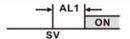
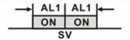
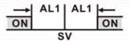
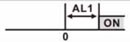
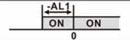
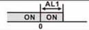
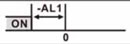
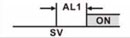
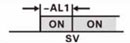
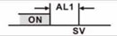
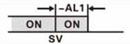
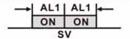
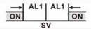
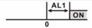
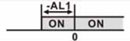
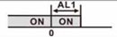
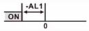
7.Alert type [ ]
]
|
The set value |
Alarm types |
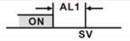
Positive alarm value (AL1) |
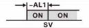
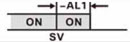
Negative alarm value (-AL1) |
Deviation alarm/absolute alarm |
|
0 |
No alarm function |
NO Output |
|
|
|
1 |
Limit deviation |
|
|
Deviation alarm |
|
2 |
The lower limit deviation |
|
|
Deviation alarm |
|
3 |
Interval alarm |
|
Has been to OFF |
Deviation alarm |
|
4 |
Out-of-range alarm |
|
Has been to OFF |
Deviation alarm |
|
5 |
Absolute limit |
|
|
Absolute alarm |
|
6 |
Absolute lower limit |
|
|
Absolute alarm |
|
10 |
No alarm function |
NO Output |
|
|
|
11 |
Attached standby upper limit deviation |
|
|
Deviation alarm |
|
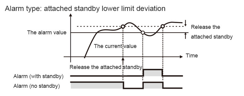
12 |
Attached standby lower limit deviation |
|
|
Deviation alarm |
|
13 |
Alarm in the standby range |
|
Has been to OFF |
Deviation alarm |
|
14 |
Alarm outside standby range attached |
|
Has been to OFF |
Deviation alarm |
|
15 |
Attached upper limit of standby absolute value |
|
|
Absolute alarm |
|
16 |
The lower absolute value of standby is attached |
|
|
Absolute alarm |
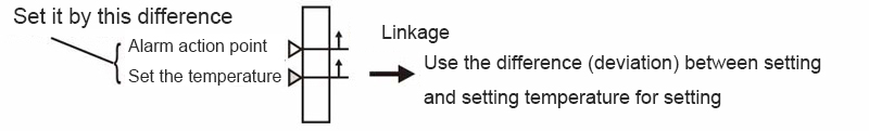
Use when you want to interact with the set temperature.
The alarm action point will change with the change of setting temperature.
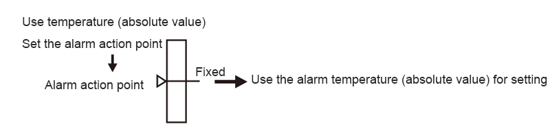
No need to interact with the setting temperature.
The attached standby function means that the alarm will not be ON even if the condition of "ON" is reached from the current value beyond the alarm range until it enters the next alarm range.
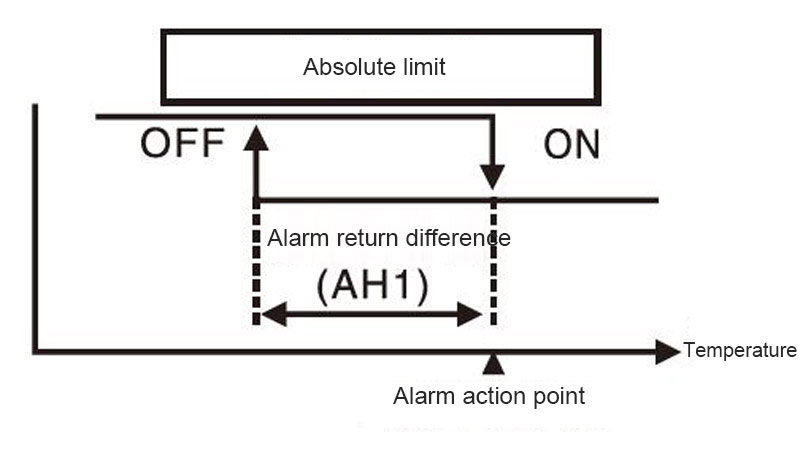
8.Alarm return difference [ ]
]
Used for the difference needed to return to a non-alarming state from an alarming state.
If the alarm action point is 120 ° C, the alarm return difference value is set at 20 ° C. When the temperature reaches above 120 ° C, it will be in the alarm state; when the temperature falls below 100 ° C, it will return to the non-alarm state.
※ The setting range is 0~100℃.
※ Factory default is 1℃
Fault message indication
|
Message |
Instructions |
Elimination method |
|
HHH |
Input disconnected or out of range |
Please check the input signal for error |
|
LLL |
Input disconnected or out of range |
Please check the input signal for error |
Matters needing attention
1.In order to eliminate inductive interference, please wire the product separately with high-voltage lines, power lines, etc.
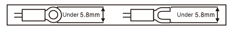
2.Use the M3 terminal in the following shape.
3. Please use the power switch or circuit breaker when turning off the power to the product.
4. Please install the switch and circuit breaker nearby for the operator to operate.
5. If the product is used as temperature indication or adjustment, it should not be used as other instruments.
6. When using the thermal resistance (RTD) sensor, 3 wires should be connected. If you want to extend the wire, you must use the same type and length of wire connection.If the impedance of the line is different, it may cause temperature deviation.
7. When the power line and the input signal line have to be installed closer, please add a filter at the power end and shield the signal line.
8. Keep away from high frequency equipment (high frequency welder, high frequency sewing machine, high capacity SCR controller)
9. When the measurement input is switched on, HHH or LLL will be displayed if any error occurs. At this time, check whether the input is wrong after power off.
10.This product is used in the following environments.
①Indoor ②Pollution level 2
③Altitude 2000m below ④Installation classification LL
※ If you violate the above precautions, it may cause product failure. Please be sure to comply.
Product parameters
|
Power supply voltage |
①220VAC 50/60Hz ②100-240VAC/DC |
|
|
Range of allowable voltage variation |
90-110% of the supply voltage |
|
|
Consumed power |
Below 8VA |
|
|
The input specifications |
Thermocouple |
K E J |
|
Thermal resistance |
Pt100 Cu50 |
|
|
Display precision |
±0.5% |
|
|
The input specifications |
The relay 250VAC 5A is on and off |
|
|
Below SSR 12VDC±2V 20mA |
||
|
Analog voltage output (0-5V, 1-5V) |
||
|
Analog current output (0-20mA, 4-20mA) |
||
|
SCR Silicon controlled output (zero crossing output, phase shifting output) |
||
|
Alarm output |
The relay 250VAC 5A is one NO |
|
|
The control mode |
Bit control, PID control |
|
|
Sampling period |
100ms |
|
|
Relay life |
Mechanical more than 2.5 million times electrical more than 100,000 times |
|
|
Withstand voltage |
2000VAC 50/60Hz 1 min (between terminals and housing) |
|
|
Resistance to vibration |
5~55Hz(cycle 1 minute) amplitude 0.75mm X,Y,Z all directions for 2 hours |
|
|
Insulation impedance |
More than 10 om Ω MEGA (500 VDC) |
|
|
anti-interference |
Simulated square wave generator interference (pulse width 1 m) ±2KV R phase S phase |
|
|
Power failure memory |
About 10 years (non-volatile semiconductor memory) |
|
|
The surrounding environment |
Operating ambient temperature |
When stored at -5~40℃ :-10~50℃ |
|
Ambient humidity in use |
35 ~85% storage :35 ~85% |
|
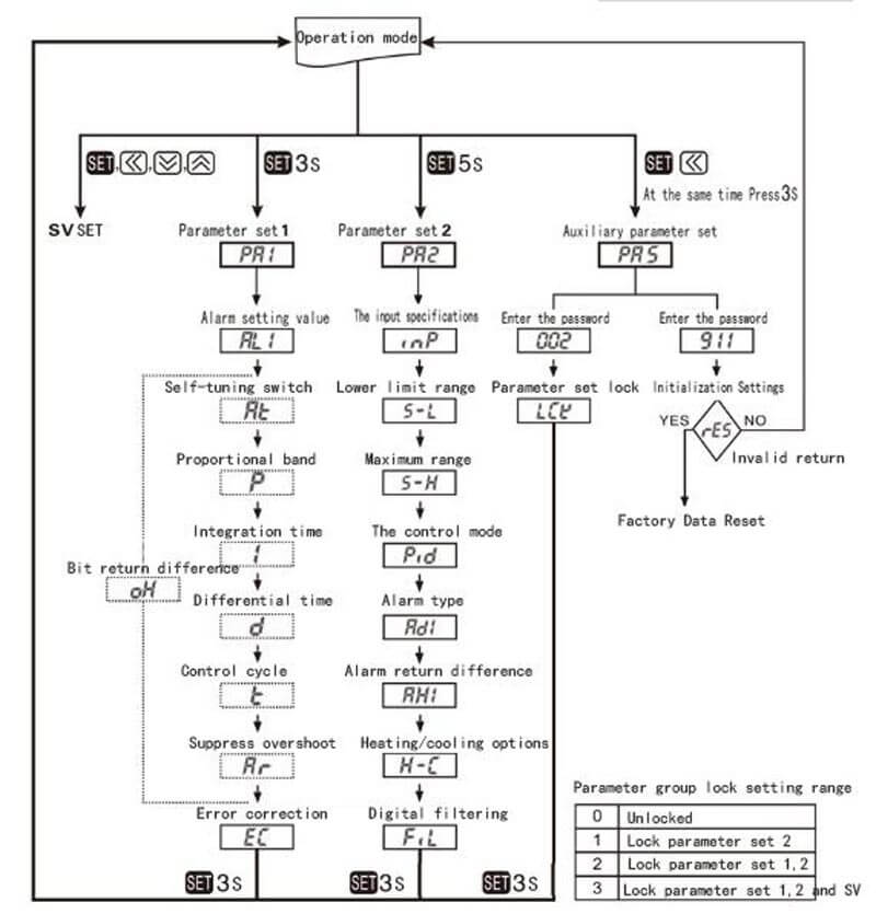
Parameter Settings
1.All parameters
Parameter group lock setting range
|
0 |
Unlocked |
|
1 |
Lock parameter set 2 |
|
2 |
Lock parameter set 1,2 |
|
3 |
Lock parameter set 1,2 and SV |
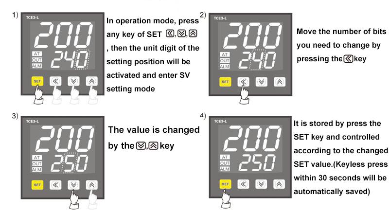
※In any parameter group, press the limit for 3 seconds, save the set value and return to operation mode.(SV setting, just press the key to return to operation mode once)
※ After entering the parameter setting mode, if no key is pressed within 30 seconds, the operation mode will be returned automatically. The changed parameters cannot be saved and the parameter values before the change are still maintained.
※Pressto enter the next set of parameters.
※The parameter of the dotted line marker will be shown or hidden as control methodis in the state of""or"".
※Parameters are correlated with each other. Please make sure to set them in the order of "Parameter group 2" → "Parameter Group 1" → "SV Setting".
※There are parameter group lock and parameter initialization functions in the auxiliary parameter group, please use with caution.
2.Parameter Group 2 [PA2]
3Parameter Group 1 [PA1]
4.Set the SV
5.Parameter group lock
While holding down for 3 seconds, enter password 002 to enter parameter group lock [
 ].
].
※Parameter groups can be viewed when locked, but the lock setting range of parameter groups cannot be modified
Parameter group lock setting range
|
0 |
Unlocked |
|
1 |
Lock parameter set 2 |
|
2 |
Lock parameter set 1,2 |
|
3 |
Lock parameter set 1,2 and SV |
6.Parameter initialization
All parameters initialize factory Settings.At the same time, press and hold for 3 seconds, enter password 911, and enter the initialization Settings[ ]
]
When selected as " " the previous state will be returned; when selected as "
 " all parameters will be restored to factory Settings.
 Español
 中文
中文 English
 Pусский
 Português
 عربى
عربى